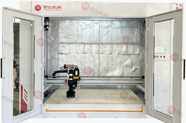
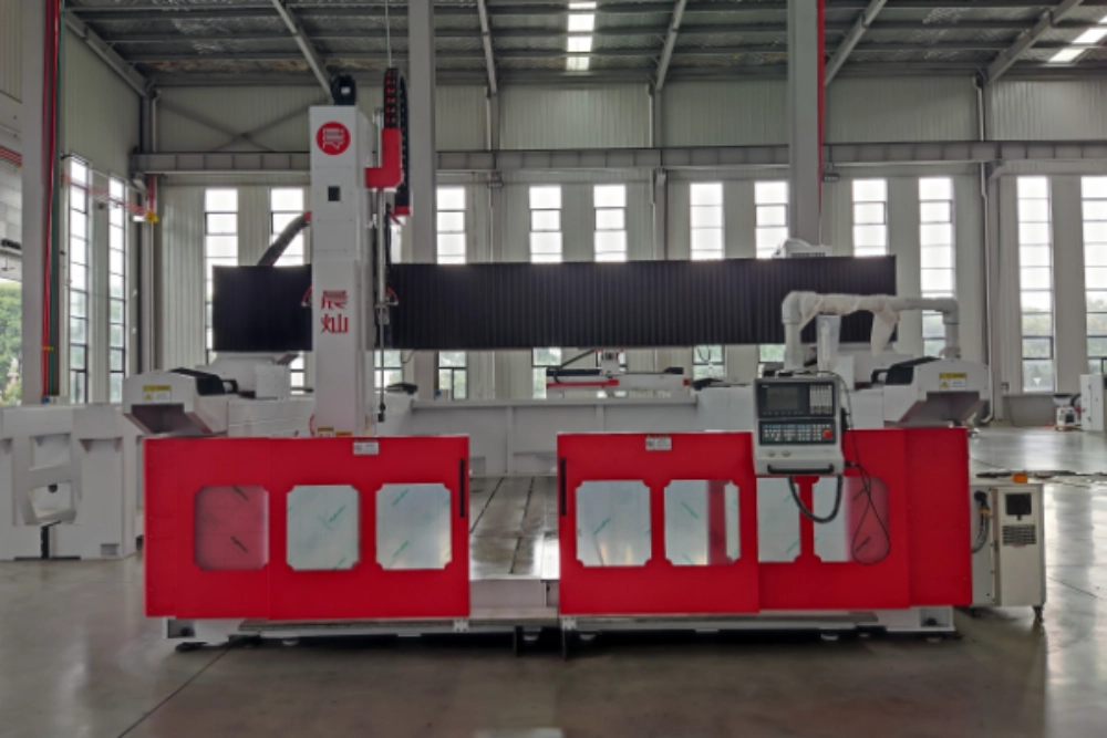
Foam is easy to cut, but accurate foam patterns are not automatically easy to produce. Long cutters can deflect, low-density blocks can tear, fine dust can be recut into the surface, and aggressive roughing can leave the finishing pass with uneven stock. For a CNC Router for Foam Patterns, the real target is the finished pattern after roughing, finishing, sanding, and any sealing step required downstream. That means chip load, cutter reach, dust extraction, fixture pressure, and finishing allowance should be tuned as one process instead of being optimized separately for the fastest cycle time.
The Checks That Matter After Roughing
- Foam pattern accuracy depends on chip load, cutter reach, finishing allowance, and fixture stability.
- Dust control affects visibility, tool temperature, recutting risk, and final surface quality during long roughing cycles.
- A production trial should judge the finished pattern after sanding or sealing, not only the roughing speed.
Foam Machining Looks Easy Until the Surface Becomes the Mold Reference
Foam patterns are often treated as forgiving because the material removes quickly. In mold and pattern work, that assumption creates avoidable errors. Soft foam can compress under clamping pressure, long tools can vibrate, and aggressive roughing can leave marks that increase hand finishing time.
The practical goal is not simply removing foam fast. The goal is a stable reference surface that can support coating, casting, composite layup, or downstream inspection without excessive manual correction. The machine should therefore be evaluated by finished accuracy, repeatability, and rework level rather than by cutting speed alone.
Chip Load Should Match Foam Density and Cutter Geometry
Too little chip load can rub the foam and generate heat instead of producing a clean chip. Too much chip load can tear beads, drag material, or overload a long tool. The correct setting depends on foam density, cutter diameter, flute geometry, spindle speed, feed rate, and the required surface finish.
Feed rate and spindle speed should be judged by the chip and surface they produce. Stable foam CNC router mold carving performance depends on shearing the material cleanly instead of rubbing it, especially when long tools and low-density foam make heat buildup and deflection easier to miss.
Finishing Allowance Protects the Final Shape
Leaving a controlled allowance after roughing gives the finishing tool a consistent amount of material to remove. If roughing runs too close to final size, vibration marks and deflection errors can remain visible after finishing. If the allowance is too large, the finishing pass becomes slow and may load the tool unevenly.
For large foam patterns, a reference allowance often sits in the low millimeter range, but the exact value should be adjusted by foam density, cutter length, sealing plan, and surface requirement. The final value should be confirmed with sample material instead of copied from an unrelated job.
Foam Pattern Routing Checklist
| Variable | Why It Matters | What to Check During Trial |
| Foam density | Changes chip formation, support strength, and surface behavior | Edge tearing, compression marks, and dust character |
| Cutter reach | Long tools amplify vibration and deflection | Rib marks, surface waves, and corner drift |
| Roughing allowance | Protects the final surface for finishing | Consistent material left for the finish pass |
| Dust extraction | Keeps the kerf clear and the surface visible | Heat, recutting, and operator visibility |
Product Fit and Trial Conditions
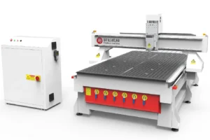
For deep foam blocks, a foam mold CNC machine should be matched to cutter reach, work envelope, extraction access, and finishing strategy. The broader high-speed mold CNC machine becomes relevant when the process also needs tighter surface control, stronger repeatability, or a more demanding mold-making duty.
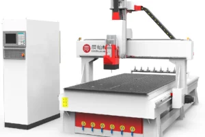
A serious trial should include roughing, finishing, narrow ribs, broad surfaces, and dimensional inspection after the foam relaxes from clamping. That is the fastest way to prove whether the process is stable enough for repeat production rather than only for a clean sample cut.
Where Foam Routing Projects Commonly Lose Time
One common loss point is underestimating hand-finishing time. A fast roughing cycle has little value if it leaves a surface that takes hours to repair. Another mistake is ignoring tool wear because foam seems gentle. Abrasive fillers, surface skins, coatings, or composite-backed boards can shorten tool life much faster than expected.
The routing plan should define the acceptable sanding or sealing allowance before machining begins. That keeps the machine program, operator expectation, and final pattern tolerance aligned from the first sample to the last production piece.
Trial Cutting and Acceptance Details
CNC router evaluation should use the customer’s real material, because performance changes with density, surface skin, coating, adhesive layer, cutter reach, and fixture method. A clean demonstration on easy stock does not prove that production parts will hold tolerance after several hours of cutting.
A stronger trial includes straight cuts, internal corners, small holes, long edges, roughing, finishing, and inspection after the part is removed from the fixture. If dust, heat, or vibration appears only after repeated cuts, the setup still needs adjustment before it is accepted for production.
Dimensional review should include both the first sample and the last sample in a short run. That exposes tool wear, spoilboard condition, vacuum stability, and whether the operator can repeat the setup without relying on one perfect demonstration.
Questions for Machine Configuration
What material thickness, density, and surface layer must be cut most often?
Which tolerance matters most: edge straightness, hole position, surface finish, or repeatability?
How will dust extraction, tool change, fixture setup, and operator access be handled during a normal shift?
Will the parts need sealing, coating, bonding, sanding, or measurement after machining?
Operating Checks for CNC Router
Tooling records should be part of the acceptance file. Cutter diameter, flute type, spindle speed, feed rate, step-over, cutting depth, and tool life give the workshop a repeatable starting point after delivery. Without those records, the first production week often turns into trial and error.
Fixture repeatability deserves the same attention as machine motion. Vacuum loss, clamp interference, spoilboard wear, and panel movement can all create defects that look like CNC accuracy problems. A stable workholding method often reduces rework more effectively than small tool-path tweaks.
Surface inspection should match downstream use. A part that will be bonded needs a clean edge and low dust. A part that will be painted needs surface consistency. A mold reference needs dimensional stability after finishing. Each use case changes what should be accepted and what should be rejected.
Operators should also check how easily the machine can be cleaned between materials. Foam dust, composite powder, and wood chips behave differently. If the line handles multiple materials, extraction access and table cleaning time become part of real productivity.
The safest machine choice is the one that makes the hardest required geometry repeatable, not the one that looks fastest on an easy sample. The trial should therefore include the longest cutter reach, the deepest pocket, and the tightest corner that the project truly requires.
Verify Accuracy After Coating or Sealing, Not Only After Cutting
Many foam patterns receive sealer, resin, filler, or a hard coating before they become the final mold reference. Those steps can change dimensions and can either hide or amplify machining marks. A useful trial therefore measures the part after CNC finishing and again after the normal sealing and sanding sequence. If the part is intentionally left oversize for coating, that allowance should be stated clearly in the machining plan.
Tool reach should be included in the accuracy review. Deep pockets and tall foam blocks often require long cutters, which makes deflection and vibration more important than spindle power alone. The same feed rate that works on a short tool may leave scallops or dimensional drift when the reach increases.
Fixture pressure deserves equal attention because soft foam can deform while clamped and relax after release. Dimensional inspection should therefore include at least one critical feature after unclamping. When the finished, unrestrained pattern stays inside tolerance and needs only the planned amount of hand finishing, the process is ready for repeat production.
أسئلة متكررة
What cutter works best for foam CNC routing?
The best cutter depends on foam density, desired surface finish, and tool reach. Single-flute or specialized foam cutters are often used for clean chip evacuation, but the final choice should always be tested on the actual material stack.
How much finishing allowance should be left on foam patterns?
A small controlled allowance is usually better than roughing directly to the final surface. The exact value depends on density, cutter length, coating plan, and surface tolerance, so it should be validated in sample cuts.
Why does dust extraction matter when foam is easy to machine?
Dust affects visibility, heat, recutting, operator cleanliness, and downstream coating quality. Fine debris can also contaminate bonding or sealing steps after machining, so extraction belongs in the process plan from the beginning.
Approve the Process at the Finished Pattern Stage
Final selection should compare the BS سلسلة الاقتصاد and other suitable configurations against the largest foam block, longest cutter reach, dust-control method, finishing allowance, and the inspection standard used after the pattern is unclamped, sealed if required, and finished.
الاتصال تشينكان for more information.