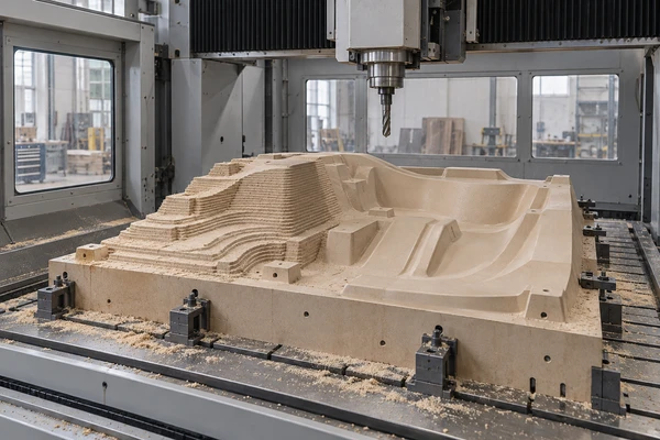
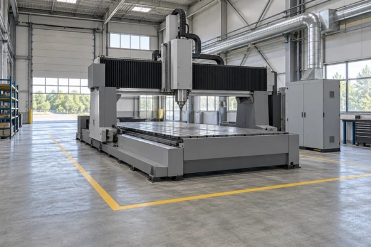
Five-axis machining can reduce repositioning by changing the tool angle relative to the mold, allowing more surfaces to be machined in one setup. The benefit depends on rotary travel, tool reach, fixture clearance, machine calibration, and collision-free access. Some features can be reached with indexed 3+2 positioning; others benefit from simultaneous five-axis motion.
إن SF2640A-5S High Speed 5 Axis CNC Machine For Mold Making is one option to evaluate once the machining requirements are defined. Match the mold and fixture to the usable five-axis working envelope, then check access to steep walls, deep cavities, and finishing surfaces. Axis travel alone does not describe the space available at every tool angle.
Keeping roughing, semi-finishing, and finishing on a common workpiece datum can reduce manual handling and repeated datum transfers. For example, an accessible inclined sidewall may be machined by tilting the head rather than lifting and re-clamping the mold. This is an illustrative scenario; the actual setup reduction must be verified for the part.
Key Takeaways
| Factor | Three-Axis CNC | Five-Axis CNC | Setup implication |
| Surface access | Fixed tool direction | Indexed or changing tool direction | Check each feature |
| Typical constraint | Access and tool reach | Collision and rotary limits | Validate safe access |
| Acceptance | Dimensions after re-fixturing | Dimensions across tool angles | Inspect a common datum |
Five-axis orientation can reduce re-fixturing when inclined or curved surfaces are reachable from the original setup.
The gain depends on the machine configuration, usable working envelope, fixture clearance, tool rigidity, and validated post-processor.
Use machine simulation and first-piece inspection to decide whether indexed 3+2 positioning is sufficient or simultaneous motion adds value.
Tool Orientation Reduces the Need to Re-Fixture the Mold
On a three-axis machine, a surface facing away from the tool may require re-fixturing, a different fixture, or a longer cutter. Every new setup adds handling and requires the workpiece datum to be recovered. Five-axis machining changes the relative orientation of tool and workpiece so that more surfaces may be reached without a new setup.
Machine architecture matters. A rotary-head machine changes tool orientation, while a table-based system rotates or tilts the workpiece. For large molds, the objective is to retain stable workholding while reaching the required surfaces. Undersides, clamped areas, or features outside the safe working envelope may still need another setup.
Keep the Cutter Near a Favorable Contact Angle
Tilting a ball-nose cutter can move contact away from its low-speed center and may allow a shorter tool to clear a nearby wall. The appropriate lead or tilt angle depends on the cutter, material, surface geometry, and cutting conditions. A favorable angle can improve access and cutting stability, but it does not guarantee a better finish.
Indexed 3+2 and Simultaneous Motion Solve Different Problems
In indexed 3+2 machining, the rotary axes position the tool or workpiece at a selected angle and remain stationary during the cutting pass. This is suitable when one angle provides access to an entire region. Simultaneous five-axis machining changes orientation during the cut, which is useful when access or the desired contact angle changes along a surface. Choose the simplest motion that meets the geometry and finish requirements.
Fixture Datums and Toolholder Clearance Set the Real Limit
Workholding must resist the cutting loads produced at different tool angles. Include clamps, risers, the table, spindle head, toolholder, and cutter in clearance checks. A tool tip may reach a cavity while the holder or head cannot pass its wall. Five-axis access therefore needs to be checked as a complete machine-and-fixture arrangement.
Before programming, identify fixture height, the deepest features, required tool lengths, and critical orientations. If a clamp must be moved, define how the part remains secure and how the datum will be checked. Re-probing may confirm location, but it does not automatically remove fixture movement or machine calibration errors.
Long Tools Can Erase the Benefit of Better Access
A shorter cutter generally offers greater stiffness when other conditions are comparable. Reorienting the tool may reduce the overhang needed to reach a wall or curved surface. Deep cavities can still require long tooling, however, and deflection or chatter may limit the benefit of improved access.
Evaluate tool gauge length, holder clearance, cutting engagement, feed direction, and required finish together. A collision-free path with a long cutter may still be usable, but it can require more conservative cutting conditions. Compare the complete operation with the alternative setup rather than judging access alone.
Post-Processor and Collision Simulation Are Part of the Setup Plan
The post-processor must generate motion for the actual machine kinematics and controller configuration. Check the posted NC program in a machine simulation that includes the head, table, holder, cutter, workpiece, and fixture. Rotary limits, axis reversals, and any rewind or retract sequence need particular attention on long finishing paths.
Validate the setup using the machine supplier’s prove-out procedure, with controlled motion and clearance checks where appropriate. Inspect surfaces machined at different tool angles and transitions between regions. Simulation supports this process but does not replace correct offsets, calibration, workholding, or first-piece inspection.
Where CHENcan Fits the Machining Discussion
إن SF2640A-5S High Speed 5 Axis CNC Machine For Mold Making uses a rotary-head configuration within the SF gantry-move range. Evaluate its usable working envelope and rotary travel against the mold, fixture, and tool assembly. Select the spindle, control, and other options for the actual material and process; the presence of five axes alone does not establish suitability.
To discuss your application with تشينكان, share the CAD model, overall dimensions, material, tolerances, surface finish target, and fixture concept. Mark the features that currently require repositioning and describe the existing setup sequence. These details help identify which operations could share one setup and which still need separate access.
What to Record During the First Five-Axis Trial
Number of manual setups and datum transfers compared with the existing process.
Critical tool angles, maximum tool gauge length, and minimum holder clearances.
Collision risks, rotary limits, and retract or rewind sequences resolved during simulation.
Measured dimensions on surfaces reached from different tool angles.
Total setup and machining time, surface finish, and remaining polishing or rework.
A successful trial removes a handling or setup step while maintaining the specified dimensions and finish. Record both time savings and any added programming, proving, or inspection time. This provides a practical basis for deciding whether the revised process is repeatable.
أسئلة متكررة
Does five-axis machining always eliminate repositioning?
A: No. Five-axis machining can reduce repositioning when the required surfaces remain accessible within the machine’s safe working envelope. Clamped areas, undersides, excessive part size, and limited tool reach may still require another setup.
When is 3+2 machining enough?
A: Indexed 3+2 machining is often sufficient when one fixed orientation provides safe access to an entire region. Simultaneous motion is useful when the tool direction needs to change during the cut.
Why does tool length matter to repositioning?
A: Reorienting the tool may reduce the length needed to reach a feature. If a deep cavity still requires substantial overhang, evaluate deflection, chatter, and cutting conditions before assuming that five-axis access will improve the process.
What should be simulated before cutting?
A: Check the posted program against the machine kinematics, tool and holder, workpiece, fixture, axis limits, and rotary transitions. Verify critical clearances and offsets on the actual machine during prove-out.
What project data helps with machine selection?
A: Provide the CAD model, material, mold dimensions, fixture height, tolerances, surface finish target, tool access requirements, and current setup sequence.