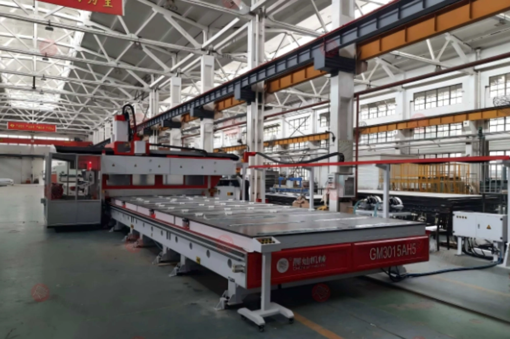
Larger beads raise deposition output but also increase minimum feature size and stored heat, while inadequate cooling raises the risk of warpage and post-machining movement. Large-format pellet extrusion builds a mold by placing thick roads of molten polymer rather than the fine filament lines familiar from desktop printing. The process can deposit material quickly, but every bead carries heat, shape, and internal stress into the part. Bead width and cooling time therefore affect much more than surface appearance.
A mold that looks complete at the end of printing may continue to contract, twist, or settle as its interior cools. If machining begins too early, the finished surface can move afterward. If the bead is too large for a thin feature, the slicer may leave gaps or overfill corners. Stable production comes from treating deposition, cooling, and finishing as one manufacturing route.
Bead Geometry Sets the Smallest Printable Detail
Nozzle diameter, extrusion flow, layer height, travel speed, and material viscosity determine the deposited road. A wider bead raises output and can improve contact area, yet it also limits corner radius, wall thickness, and the gap that can be filled without excess material. The digital model should acknowledge that minimum feature size before slicing begins. A useful process check treats volumetric flow as the deposited cross-section multiplied by travel speed.
Layer Height Changes Bonding and Surface Stair-Stepping
A layer must press into the previous bead enough to create contact without flattening so far that dimensions grow. Excessive height leaves a weak, rounded interface. Very low height increases heat input per unit height and print time. The best value depends on nozzle, polymer, bead temperature, cooling, and whether the surface will later be milled.
For a machined mold, coarse deposition can be sensible when a consistent finishing allowance remains everywhere. The allowance must exceed bead waviness, local underfill, thermal distortion, and setup error. It should not be so large that milling removes unnecessary material for hours or exposes poorly bonded internal roads.
Corner Flow Reveals Over-Extrusion Quickly
The print head slows at direction changes. If extrusion does not respond, material accumulates at corners and raises local heat. Rounded external corners grow; internal corners may close. Toolpath planning should manage acceleration and flow together, then use a representative corner coupon to verify the result before a long mold starts.
Cooling Controls Shape Through the Whole Section
The bead surface can become firm while the center remains hot. Successive layers trap heat, especially in thick walls or compact infill. A short layer time may keep the lower material too soft to carry the next pass. A long pause can cool the interface so far that interlayer bonding weakens.
Large parts also cool unevenly. Tall thin walls lose heat faster than dense bases, while corners and changes in section thickness create different contraction paths. Air movement and room temperature should remain controlled. Direct drafts can cool one side faster and introduce bending even when extrusion settings are unchanged.
Use Temperature History, Not One Surface Reading
Infrared readings help compare surfaces but depend on emissivity and viewing angle. Embedded or contact measurements in trials can reveal how long the interior stays warm. At minimum, record melt setting, build-area temperature, layer time, room conditions, and the delay before machining. This creates a process history when a part later moves.
Plan Warpage Before Adding More Material
Adding thick walls to make a mold rigid can increase thermal mass and contraction force. Geometry may be stabilized more effectively through balanced wall placement, ribs, appropriate infill, gradual section changes, and a build orientation that avoids long unsupported shrink paths. The fixture and build surface must also resist movement without damaging release.
Material conditioning belongs in the same plan. Moisture can create bubbles, unstable flow, weak bonds, or rough surfaces in polymers that absorb water. Pellets should be stored and dried according to the adopted material process, then protected from reabsorption on the route to the extruder.
Connect Printing to CNC Finishing
إن DF2030 High Efficiency Pellet 3D Printing Equipment for Mold Making can be evaluated with a mold coupon that includes thick and thin walls, corners, a sloped surface, a machining datum, and the intended polymer. A production trial should record deposition rate, bead consistency, layer bonding, distortion, cooling delay, and the stock left for finishing rather than judging print speed alone. Published DF2030 information states that the machine is intended for composite materials with melting points below 350°C and can reach an extrusion output of up to 8 kg/h.
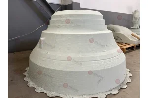
تشينكان develops CNC and industrial additive equipment for mold and pattern applications. When printed molds require machining, the coordinate strategy matters. Printed datums need enough integrity to locate the part, while the fixture must support cutting forces without distorting a hollow or warm structure.
Machine Only After the Part Reaches a Stable State
A fixed waiting time is useful only when material, geometry, room temperature, and build history remain similar. A better release rule combines elapsed time with temperature and dimensional checks at defined points. If dimensions continue to change, machining converts temporary geometry into a finished surface that may not remain true.
The cutter should remove material cleanly without reheating or pulling weak layers. Tool geometry, spindle speed, feed, engagement, extraction, and support need trials on the printed polymer. Inspect machined surfaces for voids and interlayer openings; these defects may affect sealing or coating even when the dimensions pass.
Build a Repeatable Print-to-Mold Record
A useful production record contains pellet lot and conditioning, nozzle, temperatures, bead and layer settings, flow calibration, toolpath version, room conditions, print time, mass, cooling delay, dimensions before machining, fixture, cutting data, and final inspection. Photographs at consistent stages help distinguish deposition defects from handling or machining damage.
CHENcan’s industrial 3D printer range and service information can support trials based on the real mold file, material, finishing route, and accuracy target. A difficult coupon is more informative than a decorative demonstration because it exposes thermal accumulation, narrow features, tool access, and finishing allowance within one build.
The final acceptance test should repeat the coupon, not print it once. Repeatability across builds shows whether bead size, cooling, and dimensional movement are controlled well enough for scheduling and downstream machining. A single successful mold may hide sensitivity to pellet condition, operator timing, or room temperature.
Check Internal Quality at a Machined Cross-Section
Machine or cut selected trial areas to expose bead fusion, voids, and infill contact. Compare thick and thin sections and areas printed after long or short layer times. A strong outer skin can hide weak internal contact. Cross-section evidence helps set bead overlap, flow calibration, cooling, and machining allowance for the full mold.
Use Dimensional Checkpoints During Cooling
Measure a small set of datums immediately after printing, after the surface reaches room temperature, before machining, and after finishing. The pattern of movement shows whether contraction is still active and which regions need more cooling or a different build strategy. A single final measurement cannot explain when the distortion occurred. For production release, use at least three repeat builds and define a maximum permitted datum drift over a fixed cooling interval.
أسئلة متكررة
Q1: Why does a larger extrusion bead increase pellet 3D printing speed?
A: It deposits more material per pass, but it also reduces printable detail and increases the heat carried into each layer.
Q2: Can a printed mold be milled immediately after printing?
A: Machining should wait until temperature and dimensions are stable; otherwise the part may continue to contract after finishing.
Q3: How much machining allowance should a pellet-printed mold have?
A: It must cover bead waviness, distortion, underfill, and setup error while avoiding unnecessary cutting, so it should be proven on the adopted process.
Q4: Why can thick printed walls warp more than expected?
A: Thick sections store more heat and create larger contraction forces, particularly when cooling is uneven or geometry is unbalanced.
Q5: What should be included in a large-format 3D printer trial?
A: Use the real polymer and include representative walls, corners, slopes, cooling time, datums, machining allowance, dimensional checks, and repeat builds.