
The working envelope of a CHENcan five axis router is the space within which the tool can reach the work at the required angles with the work and its fixture in place.
Axis travel
The theoretical work envelope is defined by the translation of each linear and angular axis of the machine. The actual work envelope is limited by the physical size of the machine worktable, tooling, spindle housing, and any fixtures.
The axes are individual directions of motion. When determining the theoretical work envelope the limit of each axis is measured. In practice, the actual work envelope is somewhat smaller than the theoretical work envelope.
Table position
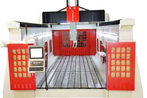
Check that the table has room for the fixture and workpiece, including clamps that extend past the edge of the part. The height should be a convenient one for loading and unloading work.
“Tee slots” may be provided for direct clamping of work, or the fixture may be bolted down to plain tables, using tapped holes.
The table should be protected from damage from the tool, and scrap material produced in machining should not be allowed to accumulate.
The size of work that can be machined depends on the size and shape of the work and the type of cutting operation to be carried out, and in some cases the shape of the fixture.
Tool length
The effective length of a tool assembly is measured from the gauge line of the spindle nose to the tip of the cutting tool. In general the effective length of a tool assembly should be kept as short as possible, consistent with the length of cut.
The straight line distance from the tool tip to the gauge line shall be compatible with the working envelope.
The extent of the tool assembly must be taken into account for the entire range of motion of the spindle head. It is not sufficient to identify the limits of the axis movements with reference to the spindle nose alone; the space taken by the tool assembly and the tool holder must be checked with the spindle head at the end of the axis motions.
With a tool changer or alternative tool holders, the working envelope must reflect the geometry of the tool that is to be used.
Tool holder clearance
The details of tool changing or tool clamping mechanisms are not important here but the accurate location of the tool in the machine is critical.
The tool point and the tool axis must be known and must remain in a known relation to the machine guideways at all times.
If the tooling is not sufficiently stiff or accurately located, the actual path of the tool point when subject to cutting forces is not predictable.
Tool holder outer geometry must be known to avoid interference with the work in deep pockets.
Tool clearance is the distance from the tool axis or spindle to the closest machine part that may touch the workpiece when the tool is in contact with the work.
The minimum clearance may be determined by the tool holder radius, spindle nose, spindle housing, quill, z-axis head structure.
Minimum R (tool radius) is limited by the minimum inside radius and depth of pockets or contours.
Approach and withdrawal
To remove material without a clash, tool approach and withdrawal are important. The approach is the space that a tool requires to move into the cut. The planned approach must ensure that the tool can attain the correct feed rate on the cut surface. The withdrawal is the space that the tool requires to move away from the cut. The tool must be able to withdraw without clashing with other machine components. Sometimes material needs to be removed before the finishing operation, so that the tool can withdraw. When using a five axis machine, the machine tool structure may interfere with the workpiece or fixture. This interference is known as a clash.
Models of the setup
To determine the workable volume of the machine tool the model of a typical workpiece and fixture is established in the machine coordinate system. The model evaluates the workable volume of the particular machine tool within the surrounding area, and includes interactions of the workpiece and the fixture with the machine tool.
For the correct design of the tool path for the workpiece and fixture given, it is necessary to know the workable volume of the machine tool (the working envelope). The workspace of the machine tool and the shape of the workpiece and fixture must be evaluated together.
The working envelope depends strongly on the design of the machine tool and its kinematics. The constraints are the strokes in the axes and the ability of the machine tool to supply the required angles of the tool.
The limits of the axes need not be fully used in a particular design, because sometimes the requirements of an industrial process, such as fixturing and loading, prevent the full use of the strokes.
All the axes combine, and the tool often can reach a point in space from different directions.
Proof of reach
This requires a knowledge of the working envelope which is a three-dimensional shape.
The graphical method consists of drawing the limits of the working envelope in two or three planes and then plotting the profile of the work, with the spindle positioned at the correct angle, onto these planes. For five axis applications, the extra complexity of varying the angle of the spindle, means that graphical methods become very difficult.
Use an accurate model of the proposed machine, tool assembly, workpiece and fixture. Simulate the programmed motion with the intended work offset and check for collisions throughout the path. The simulation program should also display the actual cutter position and orientation to check that the tool cuts the work with the required approach angle.
Software is available for this simulation either as stand-alone products, or as an integrated part of a CAM system.
Preparing an enquiry
إن CHENcan SF2030Q-5S product page lists axis stroke and five axis working size separately. For the listed configuration, the Z axis stroke is 1200 mm and the listed five axis working size in Z is 800 mm. Ask CHENcan for a layout review for the exact machine, fixture and tool assembly.


