Plan modular eVTOL composite tooling by defining the tool’s duty, mapping likely design changes, and protecting surfaces where a joint would affect geometry or sealing. Then design repeatable module interfaces, machining access, and inspection together. A replaceable section is valuable only if the assembled tool still meets the released requirements after manufacture, use, and replacement.
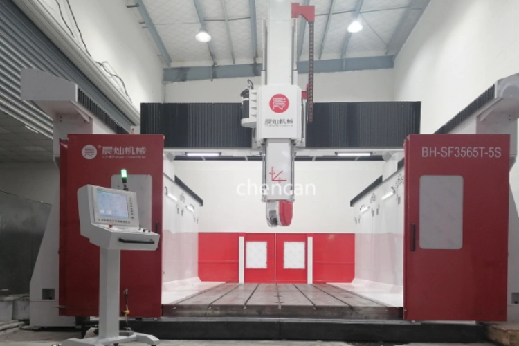
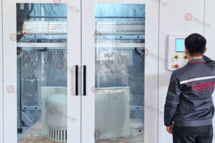
Pellet printing can produce a near-net-shape blank, while five-axis CNC machining can finish working surfaces and locating features. First distinguish a master pattern, a layup or cure mold, and a trim fixture: their thermal, vacuum, loading, and surface requirements differ. This article addresses planning the tool; successful machining alone does not establish qualification of an eVTOL component or manufacturing process.
Map Revision Risk and Critical Surfaces Before Splitting the Tool
Mark likely revision areas on the released model, such as local inserts, access openings, bosses, or edge details. On a second view, identify the mold face that controls part geometry, seal lands, datum features, and regions sensitive to joint steps or surface discontinuity. Place candidate module boundaries against both maps rather than dividing the model into equal blocks.
Keep critical surfaces continuous where practical and locate joints where they can be accessed, inspected, and maintained. A replaceable insert may be more appropriate than splitting a broad working surface. Check usable print and machining envelopes, transport-package dimensions, lifting arrangements, and storage early. Review module mass and support needs alongside geometry; a section that fits the machine may still be difficult to handle or fixture.
Define the Tool Duty Before Requesting a Machine Quote
Specify whether the tool serves a fit check, visual model, layup, cure, or trimming operation. Record the part material, expected cycles, peak temperature, dwell time, heating and cooling rates, vacuum or pressure conditions, surface requirements, and dimensional acceptance criteria. Define the inspection temperature and whether geometry is required in the free or supported state. These conditions establish the material and validation requirements.
CHENcan describes industrial pellet printing for nonmetal feedstocks and composite materials. Confirm the specific material grade and printer configuration before selecting a route. Extruder temperature capability does not establish the printed tool’s usable service temperature. The printed structure, joints, inserts, coating, and release system must work together through the intended cycle; high-temperature or autoclave suitability cannot be assumed from build size or a generic material name.
Design Repeatable Joints with Thermal Behavior in Mind
Check fastener access, assembly order, approved lifting provisions, dust extraction, and access for tools and inspection equipment. Design wall thickness, internal support, and inserts to carry clamping and machining loads. Where vacuum integrity matters, define a sealing arrangement and leak-test method. Bolts that pull a flexible module into alignment can conceal distortion rather than create a repeatable assembly.
Use a defined datum scheme and suitable locating features, such as machined pads, pins, or keys, to control module position. Distinguish locating from clamping and avoid unintended overconstraint. Assess differential thermal expansion across printed directions, inserts, support frames, and adjacent modules. Agree whether interfaces must accommodate movement or restrain it, and validate the assembled geometry under the relevant process conditions.
Assign Machining Allowance by Feature
A uniform stock allowance may add inaccessible material in one region and leave insufficient cleanup stock in another. Printed shrinkage, warpage, surface waviness, and later conditioning can change the usable blank. Plan any conditioning or thermal stabilization recommended by the material and process suppliers before final machining, and verify the blank rather than assuming that nominal print dimensions were achieved.
Mark allowance separately for the mold face, seal lands, holes, locating pads, and surfaces allowed to remain as printed. Account for coating thickness where it affects final dimensions. Check access with the actual cutter, holder, spindle head, fixture, and support arrangement. Validate critical orientations, rotary limits, and posted NC motion before cutting; added stock cannot compensate for inaccessible geometry.
Choose the Finishing Sequence Around Workholding and Datums
If the complete tool fits the usable five-axis envelope and can be supported repeatably, one option is to machine module interfaces, assemble the sections, and finish critical continuous regions in assembly. If modules must be finished separately, establish shared references and an assembly-inspection plan. Define which surfaces are accepted individually and which require inspection only after assembly.
The assembled route depends on fixture stability and access; the separate route depends strongly on interface accuracy and repeatable assembly. Use indexed 3+2 positioning where one orientation provides adequate access, and simultaneous motion where changing orientation during the cut adds value. CHENcan offers multiple five-axis configurations; assess the most restrictive real feature and support arrangement, not only nominal axis travel.
Plan Dimensional and Process Validation Before Printing
Define the coordinate system, measurement targets, accessible datums, inspection temperature, and instrument capability across the full tool span. Measure module interfaces and the assembled working surface using the agreed alignment method. Where the tool is used under vacuum or elevated temperature, include appropriate leak checks and thermal-cycle validation. A room-temperature surface scan alone does not demonstrate stability throughout a cure cycle.
Give every module a permanent identity and record assembly repeatability where replacement is expected. Define reinspection and any required revalidation when a module, joint, material, or process changes. The responsible engineering and quality functions should decide the scope based on the affected features and approved process requirements; a local change does not automatically justify either full requalification or no further testing.
Record Shop Adjustments and Configuration Changes
Record shims, skim cuts, insert replacements, fastener changes, and seal repairs against the module and assembly revision. Evaluate their effects on geometry, stiffness, sealing, and thermal behavior before release. A practical shop adjustment may be acceptable, but it needs the required engineering disposition and an updated inspection record.
Link the module ID to the material batch, print orientation and settings, conditioning history, machining revision, coating and release system, inspection results, and authorized corrections. Keep the assembly drawing tied to the actual set in use, including joint hardware and assembly instructions. This traceability allows the next build or replacement module to reproduce the approved configuration.
Prepare a Complete Supplier Enquiry
Send the released model and drawings together with tool duty, module dimensions and mass, material specification, process cycle, allowance map, datum scheme, tolerances, and fixture concept. Include seal details, restricted cutter directions, unfinished surfaces, and difficult views of returns or hidden fasteners. State the required inspection records and the representative interface or feature to be demonstrated in a trial.
CHENcan’s product range includes industrial pellet printers, five-axis machining centers, and composite-trimming equipment. Ask the team to confirm material compatibility, usable working envelope, workholding, extraction, controller and post-processor support, and available measurement options for the proposed configuration. Keep machine selection separate from validation of the printed tooling system and the customer’s eVTOL manufacturing process.
Frequently Asked Questions
What controls are needed for an eVTOL prototype tool?
Match the controls to the intended use and approved project requirements. Even a short-life tool needs a defined material and process envelope, recoverable datums, configuration records, and suitable inspection. A fit-check model and a heated cure mold require different validation. Prototype status alone does not establish suitability for flight-related production.
Should a large eVTOL tool always be modular?
No. Use modules when they solve a defined problem such as revision cost, limited machine access, transport, or replacement. Compare those benefits with joint accuracy, sealing, assembly time, and thermal movement. If a split threatens a critical surface, consider a single-piece tool or a smaller replaceable insert.
Can the printed blank be used without CNC finishing?
Sometimes, where the as-printed surface and geometry satisfy the agreed use. Critical mold faces, seal lands, holes, and locating interfaces often need machining or other finishing. Validate the printed structure and complete surface system for the intended loads and thermal or vacuum cycle; CNC finishing does not by itself establish that suitability.