
The roughing allowance entered in CAM is not necessarily the amount of material left everywhere on a mold. Around a small internal radius, for instance, a large cutter can leave a ridge well beyond that allowance. The programmer has to find it before choosing the next operation. A CNC toolpath plan that moves directly from roughing to finishing may overlook this difference between the intended allowance and the stock the tool can actually reach.
For large foam, wood, and tooling-board molds, this article follows the stock through three stages: bulk removal, local cleanup, and surface finishing. It also covers the supports and setup information needed to carry the plan from the CAM workstation to the machine.
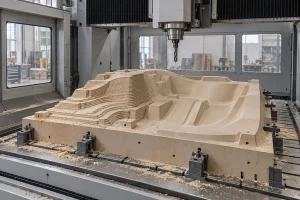
Define the stock before choosing a CNC toolpath
The CAD surface and the blank on the table are two different objects in this review. A bonded blank may have uneven edges or adhesive projecting from a joint. Model that starting condition, together with the fixture, rather than assuming a perfectly rectangular block. Otherwise, a reassuring simulation may say little about the physical setup: it cannot check a clamp that was never included.
Before calculating the first operation, check the model revision and units. Then settle one less obvious point: does the drawing describe the machined surface or the surface after sealing and finishing? The distinction matters wherever a coating changes a functional dimension. A general stock allowance cannot resolve an unanswered drawing question.
For equipment planning, compare the blank and fixture envelope with the relevant CHENcan mold CNC machine range. The usable space must accommodate the tool and holder as well as the workpiece. Nominal axis travel alone does not establish access to a deep wall or an inclined face.
Rough efficiently while keeping the next cut predictable
Start with a tool that can remove the main volume without excessive reach. Its diameter must suit the open regions of the job, while the flute length and holder clearance must suit the depths involved. A large tool can be productive on broad surfaces but leave substantial material around internal corners.
At the end of roughing, the workpiece should be ready for another controlled cut. That requires more thought than entering an allowance. Autodesk’s stock-to-leave reference distinguishes radial and axial allowance, and explains that access restrictions can leave additional material. Look at the computed stock around a pocket or corner, not only at the value in the settings dialog.
Cutting conditions need to come from guidance for the actual cutter and material, followed by a trial. A setting that works in foam has not thereby been qualified for dense tooling board. During that trial, watch the entries and corners as closely as the long open passes. Those are useful places to discover a sudden increase in engagement or an extraction arrangement that cannot collect debris from a deep cavity.
Keep supports until their job is finished
An operation that opens a pocket can also remove the material supporting a neighboring thin feature. In that situation, finishing the supported region first may be preferable. Mark the dependency on the setup sheet so that a later programmer does not reorder the operations for a shorter tool-change sequence. Review the workpiece at the stage when each support disappears, as well as at the end of the program.
Use rest machining where the previous tool left material
Rest machining uses a representation of the remaining stock to target areas left by earlier work. In the cavity example, most of the floor may already be clear, with residual material concentrated at the internal radius. A smaller tool can be assigned to that region. Sending it across the entire mold instead would include already-cleared surfaces and potentially substantial air cutting.
The result depends on the stock source. Autodesk’s remaining-stock machining guidance describes using previous operations, modeled bodies, or setup stock. Those inputs represent different assumptions. If an earlier toolpath, stock definition, or tool size changes, regenerate the dependent operations and review the remaining-stock display again.
Now return to the corner example. Is the remaining ridge shallow enough for the proposed cleanup tool, or does it extend down a deep wall? In the second case, an intermediate roughing operation may be needed before the fine tool can work safely. Inspect the entry and the overlap with the previously machined region. Calling an operation “rest machining” does not, by itself, limit how much material the cutter will meet.
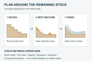
Choose finishing passes for the surface geometry
On a mold that combines a shallow floor with steep walls, the same pass pattern need not work equally well throughout. Look at the cutter contact on each region and at the spacing where the slope changes. A separate wall operation can be useful, but it creates another boundary to manage. The floor-to-wall transition therefore deserves its own inspection, rather than being judged from the appearance of the individual toolpaths.
When a trial surface looks poor, first identify what is visible. Regular geometric cusps suggest a different question from torn material or a mark caused by movement in the setup. Reducing step-over can reduce the calculated cusp, at the cost of more passes; it cannot repair a damaged cutting edge or secure a loose blank. Use cutter geometry and the allowed cusp to choose a starting value, then assess the machined surface. A cusp calculation is not a measurement of surface roughness.
Autodesk’s scallop finishing reference describes combining that strategy with contour and parallel passes. There is no requirement to use one finishing method over the whole mold. If a blend line remains, investigate its location. Moving a boundary or changing the direction of a local pass may address the cause without repeating the entire cycle.
Use five axes when access justifies them
An inclined tool can improve access to some features, but tilting also changes holder clearance and machine motion. Review whether indexed machining is sufficient or continuous five-axis movement is necessary. When comparing a CHENcan five-axis CNC center, ask for the proposed tool assembly and representative geometry to be checked together. Axis count does not replace a reach study.
Release an operation sheet that matches the program
Two files can carry similar project names while containing different tool assemblies or stock orientations. At release, compare the setup sheet with the posted program and the equipment actually prepared for the job. Resolve a mismatch before running. Follow the machine supplier’s simulation and controlled prove-out procedure, keeping guards and interlocks in service throughout.
Use this release checklist:
- Confirm the CAD revision, units, stock size, and datum scheme.
- Match tool diameter, cutting length, holder, and protrusion to the actual assembly.
- Record the roughing allowance and identify regions with extra residual stock.
- Regenerate rest machining after changes to upstream operations.
- Check finishing boundaries, protected surfaces, and transitions between strategies.
- Define the features and surface areas to inspect before coating or hand finishing.
Keep the trial results with the program. If a corner needs rework, record its location and the operation responsible. This gives the next revision a specific problem to solve. CHENcan’s technical service support can be discussed alongside the machine configuration, programming responsibilities, and trial requirements.
Preguntas frecuentes
Does every mold need rest machining?
No. An open shape that the roughing tool can reach may proceed to finishing with suitable allowance. Rest machining earns its place when meaningful stock remains in restricted regions. Check the simulated stock and actual access before adding a smaller tool and another operation simply because the CAM system offers that option.
Can the same finishing settings be used for foam and tooling board?
Not without validation. The tool geometry, stock density, material behavior, support, and required finish all matter. Start with guidance for the actual material and cutter, then test a representative surface. A successful finish on one foam grade does not establish a suitable process for a denser board or a bonded blank.
What should a supplier machining trial include?
A trial should include the features that make your mold difficult, such as a restricted corner beside a broad surface or a transition into a steep wall. Use the intended workholding concept and agree what will be inspected before cutting starts. The useful output is more than the sample itself: retain the operation sequence, residual-stock views, and measurements so the proposed process can be reviewed.
Put the sequence to work on a representative mold
A useful CNC toolpath plan explains what each operation removes, what it leaves, and how the next tool will reach it. Send the model, stock specification, fixture concept, and inspection requirements to the CHENcan application team for a machine and trial discussion. Agree the sequence on a representative job before committing a valuable full-size blank.


