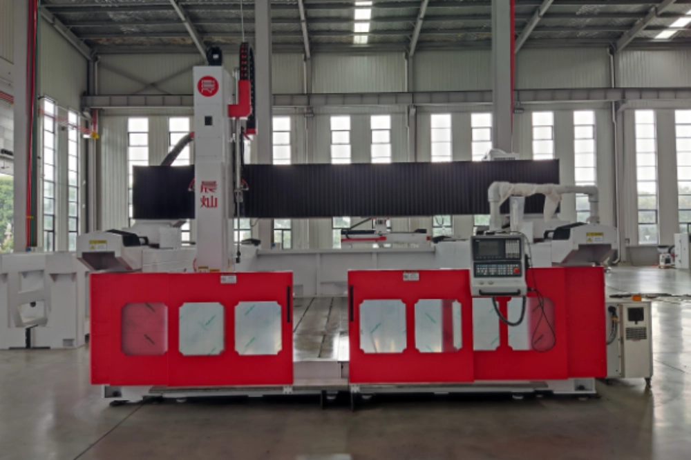
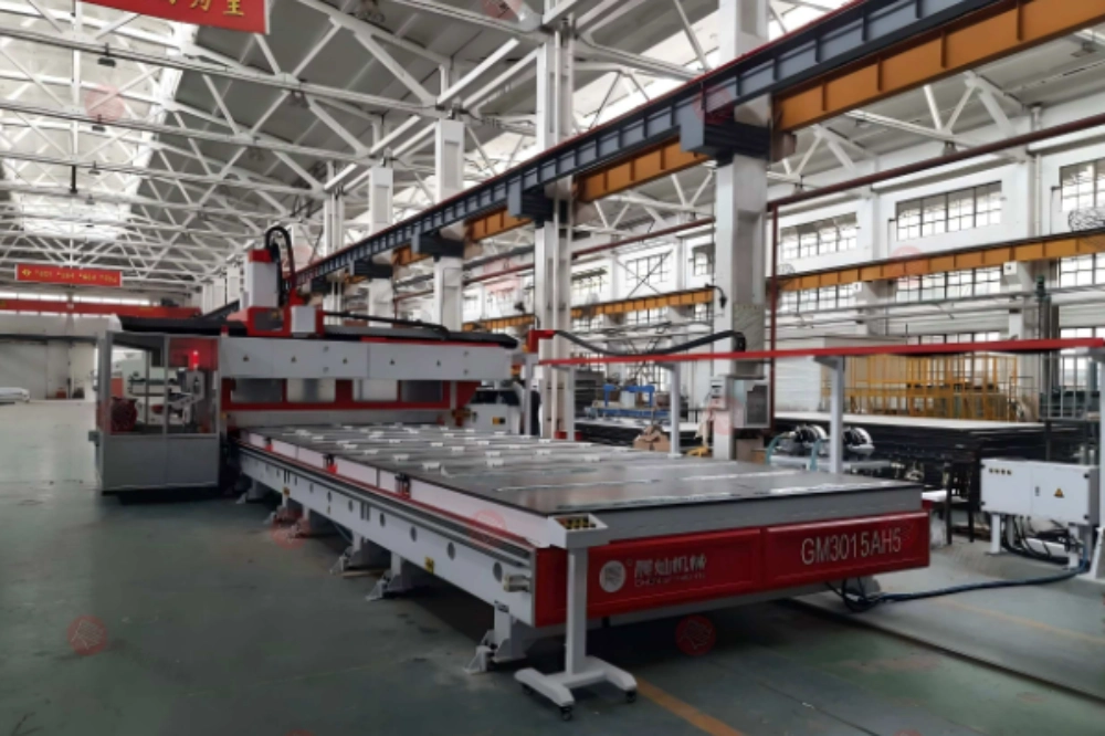
A sandwich panel is not one cutting material. The outer skins, adhesive line, and core respond differently to tool pressure, heat, dust extraction, and feed rate, so a setup that leaves a clean top face can still tear the lower skin or crush the core. For a Sandwich Panel CNC Cutting Machine, fixture stability adds another variable because large panels can lift or vibrate as cutouts reduce the vacuum area. Machine evaluation should therefore follow the complete part: edge quality on both faces, hole position, core condition, dust removal, and dimensional repeatability after the panel is released from the table.
Why Composite Panels Need a Layer-by-Layer Trial
- Composite sandwich panels require control over skin tear-out, core dust, panel hold-down, and edge straightness.
- The right machine check includes vacuum zoning, chip extraction, spindle power, tool path, and support table design.
- Cut quality should be verified on real production panel stacks before output is judged by travel speed alone.
Composite Panels Fail at the Interface, Not Only at the Cut Line
A Sandwich Panel CNC Cutting Machine must manage different material behaviors in one pass. Aluminum skin, insulation core, FRP surface, honeycomb core, and coated layers all respond differently to pressure and heat. A clean top face can still hide crushed core, delamination, or a ragged exit edge if tooling and workholding are not matched.
The first evaluation should ask what panel type is being cut, how thick it is, whether the edge will remain visible after installation, and whether dust control affects downstream bonding or sealing. Those questions are more useful than asking only for the highest cutting speed.
Hold-Down and Support Decide Whether the Tool Path Stays True
Large panels flex when support is inconsistent. Even a strong gantry cannot create a straight edge if the panel bows between support points or shifts under lateral tool force. Vacuum zones, mechanical clamps, sacrificial boards, and spoilboard flatness should be checked together.
Good sandwich panel cutting machine selection starts with the panel construction and the required edge condition. Skin material, core density, adhesive behavior, and the smallest features in the CAD file all influence whether a routing or sawing strategy will stay stable through a full shift.
Dust Extraction Is a Cutting-Quality Control, Not Only a Cleanliness Feature
Panel cores can create fine dust, stringy chips, or abrasive debris depending on the material. If dust remains in the kerf, it can heat the cutter, mark the surface, and contaminate adhesive or sealing operations. Extraction should stay close to the cutting point and should be strong enough to keep the tool path visible.
In production environments, the extraction system should be reviewed for hose routing, filter maintenance, operator access, and whether airflow can move lightweight offcuts out of position. Dust management that disturbs small parts is only half a solution.
Machine Evaluation Table
| Check Area | What to Inspect | Practical Target | Failure Sign |
| Panel support | Table flatness, vacuum zones, and spoilboard condition | Stable panel contact through full travel | Wavy edge or inconsistent depth |
| Tooling | Cutter geometry, sharpness, diameter, and runout | Low heat and a clean exit edge | Burr, core tearing, smoke, or chatter |
| Dust control | Hood position, airflow, and filter access | Kerf stays clear during cutting | Dust recuts into the edge |
| Motion stability | Gantry rigidity and acceleration | Smooth corners without overshoot | Dimensional drift or corner marks |
Where CHENcan Product Selection Fits
A Máquina de corte CNC de painel should be trialed on the customer’s layered material, including full-depth cuts and representative holes. CHENcan configurations can then be compared by hold-down stability, edge quality, cycle repeatability, and dust-control performance rather than by an easy sample board.
A useful sample test includes straight cuts, small openings, internal corners, dust behavior, and edge inspection after handling. If the edge will be sealed, painted, or bonded, the post-cut surface matters as much as the visible top face.
Two Shop-Floor Mistakes Worth Avoiding
The first common mistake is using one cutter for every panel material. A tool that works on a soft foam core may not perform well on aluminum composite or FRP-faced stock. The second mistake is ignoring spoilboard condition. A worn or uneven support surface changes cutting depth and can make an otherwise stable machine appear inaccurate.
Production acceptance should include repeated parts, not one perfect demonstration panel. Dimensional checks across multiple panel positions reveal whether hold-down, tool wear, and extraction remain stable during real operation.
Trial Cutting and Acceptance Details
Use the exact production panel stack in the trial, including the real face sheets, adhesive layer, and core. Cutting performance can change when aluminum, FRP, insulation foam, honeycomb, or coated skins are combined, so a homogeneous test board is not a reliable substitute.
Build the trial around features the factory actually struggles with: long full-depth edges, small openings, internal corners, drilled holes, and cutouts that reduce vacuum area as the program progresses. Inspect both skins and the exposed core after the panel is removed from the table.
Repeat the same geometry at different positions on the bed and again near the end of the trial run. That comparison shows whether vacuum zoning, spoilboard condition, tool wear, or dust accumulation is slowly changing edge quality or hole position.
Questions for Machine Configuration
Which panel constructions and thicknesses account for most of the planned production?
Where is the tightest acceptance limit: skin chipping, hole location, edge straightness, cut depth, or final part size?
How will full sheets be loaded, zoned, extracted, and cleared of dust between programs during a normal shift?
What happens to the cut edge next: sealing, adhesive bonding, painting, trimming, or direct assembly?
Operating Checks for Panel CNC Cutting Machine
Create a tooling sheet for each common panel construction rather than using one generic CNC recipe. Cutter type, diameter, flute count, spindle speed, feed rate, depth per pass, vacuum zone, and expected tool-change point should all be recorded together with the resulting edge condition.
Workholding should be checked at the point in the program when the panel has lost the most supporting area. Large cutouts can reduce vacuum grip and let the remaining web vibrate, even if the full sheet was stable when machining began.
Judge the cut by the next operation. Bonded edges need low contamination and consistent geometry, sealed edges need an intact skin and manageable core exposure, and visible finished edges may require a different tool path altogether.
Dust management should be evaluated for the actual mix of panel materials. Fine insulation particles, composite dust, and metal or coating debris load extraction systems differently, and cleanup time between materials directly affects usable machine capacity.
Treat the Skin, Core, and Adhesive as Three Cutting Problems
The top skin often sets the entry-quality requirement, while the lower skin reveals whether tool exit and workholding are under control. Between them, the core may melt, crumble, compress, or load the cutter depending on its material. A serious trial records defects by layer instead of using one vague label such as rough edge.
Adhesive lines can be especially misleading. They may create local heat or buildup even when the surrounding core cuts freely. If deposits form on the tool, edge quality can deteriorate gradually across several panels instead of failing immediately. Inspecting the cutter and measuring the last part in a short run helps reveal this slow drift.
Workholding should be challenged with internal cutouts and reduced remaining surface area. A full sheet may hold perfectly at the start of the program and become unstable after large openings are removed. Vacuum zones, onion-skin strategies, tabs, sacrificial support, or operation sequencing should be tested under that worst condition.
FAQ
What causes burrs when cutting composite sandwich panels?
Burrs often come from dull tooling, the wrong feed rate, unsupported exit edges, or material layers that need a different cutter geometry. Checking both top and bottom edges helps determine whether the issue is caused by tool entry, tool exit, or panel support.
Why does vacuum zoning matter for large panel CNC cutting?
Vacuum zoning keeps holding force concentrated under the active panel area. Without zoning, thin or lightweight panels may shift, bow, or vibrate during cutting, especially near edges and openings.
Should cutting trials use standard sample boards or real production panels?
Real production panels are better because skin material, core density, adhesive layer, thickness, and coating all affect cut quality. Standard boards can prove basic motion, but they cannot validate real production edge behavior.
Approve the Machine on Real Panels and Repeated Setups
O panel cnc cutting machine category should be narrowed by usable bed size, vacuum zoning, tool-change needs, extraction access, spindle configuration, and whether the machine can repeat the same result on the first and last panel of the run.