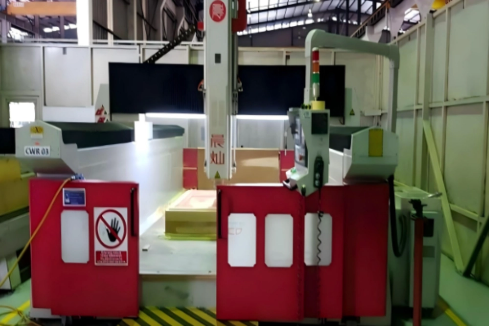
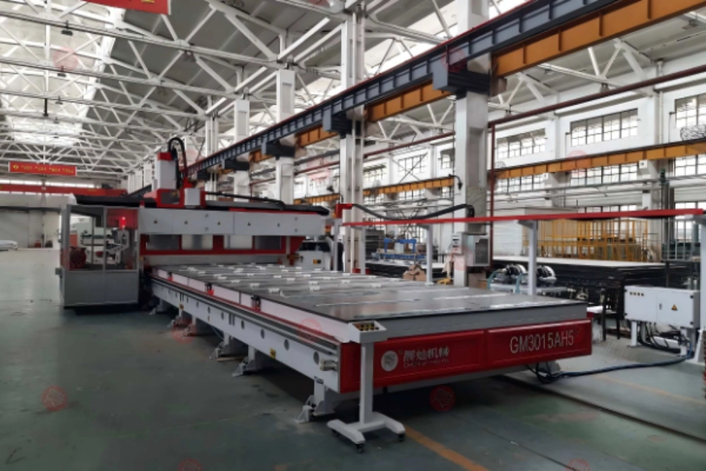
A mold maker should use a large format 3d printer when the job is large, low-volume, geometry-heavy, and suitable for thermoplastic or fiber-reinforced pellet extrusion. CNC machining remains the stronger starting point when the tool must come directly from a stable block, the required surface is difficult to reach after printing, or the material and duty cycle rule out a printed tool. In many plants, the practical answer is not one process or the other: print a near-net shape, leave controlled machining allowance, and mill the functional surfaces.
That decision should be made from the mold specification, not from machine-bed size or deposition rate alone. The useful comparison includes material, temperature, vacuum or pressure duty, surface finish, dimensional verification, annual quantity, post-processing access, and the cost of a failed build.
Begin With the Tool’s Service Conditions
Start with what the finished mold must survive. Record the process temperature, heating and cooling cycle, vacuum level or forming pressure, chemical exposure, expected number of cycles, allowable leakage, critical datums, and surface specification. A printed pattern for a one-off casting does not face the same duty as a composite lay-up mold that will be heated repeatedly.
Material is therefore a gate, not a detail to resolve after purchasing a machine. The CHENcan DF2030 pellet 3D printer for mold making processes thermoplastic pellet materials and does not print metals. Its published product information also sets a maximum material melting-point boundary below 350 degrees C. A buyer should still qualify the exact resin or filled compound for the real tool temperature, stiffness, thermal expansion, bonding, coating, and release system.
Research from Oak Ridge National Laboratory shows why this qualification matters. Its work on large-scale pellet-extrusion molds evaluates reinforced polymer systems, embedded heating, voids, interfaces, and mechanical behavior. The lesson for a factory is simple: a printable material is not automatically an approved tooling material.
Use Additive Manufacturing When Geometry Drives the Job
A large format 3d printer is most persuasive when conventional machining would begin with a bulky blank and remove most of it to reach a hollow, curved, or lightly loaded tool. Pellet extrusion builds the main volume close to the final geometry. Internal ribs, local reinforcement, lifting features, and a hollow shell can be considered during design instead of being carved from a solid block.
This route also suits design uncertainty. If the CAD surface is still changing, the ability to revise the model and rebuild may be more valuable than squeezing the lowest possible cycle time from the first part. That does not make a failed print inexpensive. It means the team can compare the cost of a controlled rebuild with the cost of reworking or replacing a large machined blank.
The strongest candidates usually share several conditions:
- low annual quantity or a prototype-stage program;
- a large envelope with substantial removable volume;
- geometry that can be printed with stable bead support;
- a material and coating system that meets the mold duty;
- accessible functional surfaces for later inspection or milling.
Keep CNC Machining When the Blank Already Fits the Job
CNC is often the cleaner choice for a relatively simple tool made from a proven board, foam, wood substitute, aluminum, or other machinable stock. If the starting blank is close to the final envelope, additive manufacturing may introduce printing, cooling, sealing, and machining steps without removing enough material or risk to justify them.
Direct CNC machining also keeps the process familiar. Datum strategy, cutter access, tool wear, probing, finishing passes, and inspection can be planned within one established route. The CHENcan 5-axis CNC center range covers mold and pattern applications where multi-face access, deep features, or changing tool orientation matter. The correct comparison is with the actual required machine configuration, not with a generic three-axis router.
CNC should remain the baseline when the tool requires a material that cannot be extruded, when the printed bead structure would create unacceptable thermal or mechanical uncertainty, or when finishing access is blocked. It may also be preferable for repeat jobs already supported by qualified stock, fixtures, programs, and inspection records.
A Hybrid Route Often Removes the False Choice
Large-format extrusion is good at placing volume; milling is good at establishing controlled surfaces. A hybrid workflow uses each process for the task it handles best. The printer creates a near-net preform with machining allowance. After the build stabilizes, CNC machining establishes datums, trims the base, finishes sealing faces, machines holes and inserts, and brings critical surfaces to the specified geometry.
CHENcan’s DF1616 printing-and-milling machine illustrates this combined route. A buyer should ask whether printing and milling occur in one setup, how the system establishes the printed preform’s datum, how chips and heat are managed, and which surfaces remain reachable by the cutter. “Hybrid” is only useful when the process plan is continuous and measurable.
Compare the Three Routes With the Same Job File
Do not compare a printer brochure with a CNC quotation built around different assumptions. Give each supplier the same CAD model, tool specification, material constraints, inspection points, finishing system, required delivery state, and annual quantity. Ask for three process plans: print only, machine from stock, and print plus machine.
| Decision factor | Print near-net shape | Machine from stock | Print, then machine |
| Starting material | Qualified thermoplastic pellets | Qualified block, board, foam, or metal | Qualified pellets plus finishing materials |
| Geometry | Best when volume and internal structure favor addition | Best when a practical blank and cutter access already exist | Best when volume is additive-friendly but surfaces need CNC control |
| Surface route | Printed texture, then seal or finish as required | Surface generated directly by cutting and finishing | Printed substrate with machined functional faces |
| Main process risk | Warpage, bonding, voids, cooling, material qualification | Tool reach, stock stability, waste, long roughing route | Datum transfer, allowance, access, combined process control |
| Evidence to request | Printed coupon and representative section | Trial cut in production stock | Complete printed-and-machined acceptance piece |
The cost model should include more than machine hours. Include material and drying, build or roughing time, cooling or rest time, fixtures, cutters and nozzles, labor, sealing, coating, inspection, scrap probability, and the value of schedule recovery after a design change. Use ranges where the process is not yet qualified rather than presenting a single optimistic payback figure.
Define Allowance Before the First Layer
Machining allowance is a design input. Too little allowance may leave bead valleys, local distortion, or a low area that cannot be recovered. Too much allowance increases printing time and recreates the material-removal burden that additive manufacturing was meant to avoid. The allowance can vary by surface according to orientation, expected distortion, cutter access, and datum importance.
The manufacturing drawing should distinguish as-printed surfaces, sealed surfaces, machined surfaces, bonded interfaces, and inspection datums. It should also state when dimensions are checked: after printing, after stabilization, after rough milling, after coating, or at final acceptance. Without those checkpoints, a team may measure different process states and argue over numbers that are not comparable.
Run a Representative Trial, Not a Decorative Sample
A useful trial includes the difficult parts of the real job: a steep wall, a flat datum, a tight internal corner, a bonded insert, a sealing edge, and an area that must be machined after printing. Print it in the proposed material, with the proposed bead size and orientation. Then complete the planned cooling, machining, sealing, coating, and inspection steps.
Record build interruptions, pellet condition, temperature settings, bead dimensions, layer adhesion observations, cooling time, dimensional movement, machining behavior, surface preparation, and final measurements. This record becomes the starting process specification. A polished display object does not answer whether a large format 3d printer can make the buyer’s mold.
Match the Equipment to the Process Route
The CHENcan industrial 3D printer range includes pellet-extrusion and printing-plus-machining configurations for industrial molds, patterns, and tooling. Selection should still begin with the user’s largest and most demanding representative tool. Check build envelope after clearances, pellet handling and drying, nozzle range, deposition control, access for machining, enclosure, extraction, controls, service access, and acceptance testing.
Before a specification is frozen, send the CAD model, intended material, service conditions, finish requirement, inspection plan, and annual quantity to the CHENcan technical contact team. The purpose of that discussion is not to force every job into additive manufacturing. It is to identify which steps genuinely benefit from printing and which should remain CNC operations.
FAQ
Q1: Does a large-format 3D printer replace a mold CNC machine?
A: Not universally. Printing places material efficiently, while CNC machining is often still needed for datums, sealing faces, holes, inserts, and controlled surface finish.
Q2: Can CHENcan pellet printers print metal molds?
A: No. CHENcan’s DF-series information identifies thermoplastic and composite pellet processing and excludes metal printing.
Q3: When is machining from stock still the better choice?
A: It is often better when a qualified blank is already close to the final shape, the material cannot be extruded, or the required surfaces and tolerances are easier to achieve directly by cutting.
Q4: What should a hybrid acceptance trial contain?
A: It should use the proposed pellet, include representative geometry and machining allowance, and complete printing, stabilization, milling, sealing, coating, and dimensional inspection.
Q5: What is the first document a buyer should prepare?
A: Prepare a job file containing the CAD model, mold duty, material limits, critical dimensions, finish requirements, expected quantity, and acceptance criteria.