A vacuum forming mold succeeds when geometry, airflow, temperature, sheet behavior, and release all work together. CNC machining establishes the mold surface, draft walls, radii, vent locations, and vacuum passages, but it cannot compensate for an undefined forming process. Before cutting, the mold maker needs to know whether the tool is male or female, what sheet will be formed, how deep the draw is, which faces are cosmetic, and how the first part will be judged.
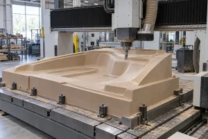
Begin With the Formed Part, Not the Tool Block
Start from the finished part and work backward through the forming sequence. Confirm trim line, flange width, undercuts, material thickness range, heating method, clamp frame, expected production volume, and the location of any inserts or secondary operations. A nominal CAD surface alone does not define these conditions.
Thermoplastic sheet stretches as it is drawn. Thickness distribution and dimensional change depend on material, initial gauge, temperature field, draw ratio, plug-assist strategy, cooling, and release. Do not apply a universal shrinkage value to every project. Use the sheet supplier’s data and the former’s production experience, then reserve a controlled first-off trial to verify the result.
The same discipline applies to mold material. Tooling board, wood, cast resin, composite tooling, and aluminum differ in heat transfer, durability, repair method, sealing requirement, and cost. CHENcan’s high-speed mold CNC machine range covers non-metal mold and pattern applications, while metal tooling may require a configuration intended for light alloys. Match the spindle, structure, extraction or chip handling, and finishing route to the actual stock.
Treat Draft as a Release Function
Draft reduces the sliding resistance between the cooled part and the mold. The required angle is not one fixed number. A shallow smooth wall may release with less draft than a deep textured wall, while a tall draw, soft hot part, rough surface, or stiff return flange may need more. Male and female tools also place the formed sheet against different surfaces as it cools.
Review draft on every pull direction, including ribs, lettering, pockets, and local bosses. Highlight faces that are nearly parallel to mold travel. If the design contains a true undercut, do not hide the problem by polishing it; change the part, use a split or removable feature, or plan a secondary operation.
Radii support both forming and machining. Sharp internal corners concentrate sheet thinning and are difficult to finish with a practical cutter. Sharp external edges can mark or weaken the part. Select radii with the sheet material and product design team, then confirm that the chosen tool can reach the surface without leaving an unplanned cusp or gouging an adjacent wall.
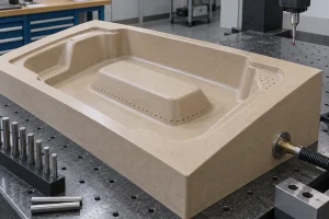
Put Vents Where Air Would Otherwise Be Trapped
Vacuum can only pull the heated sheet onto a surface if air has a path out. Vents are usually most valuable at last-to-form locations: deep recesses, tight corners, the ends of ribs, isolated lettering, and broad areas where the sheet may seal around a pocket before the trapped air escapes.
Vent diameter, spacing, and depth depend on the sheet, surface requirement, tool material, vacuum system, and cleaning method. A hole that is too large may print through onto a cosmetic face; one that is too small may clog or restrict flow. Treat published rules of thumb as trial values, not guaranteed answers.
Plan the complete air path. The surface holes must connect to grooves, a plenum, or drilled passages with enough open area to reach the vacuum connection. Avoid blind cavities that look connected in CAD but trap chips, sealer, or condensate. Mark how each passage will be drilled, cleaned, inspected, and repaired.
Finish vent holes carefully. Burrs can mark a part, and coating can close a hole that passed inspection before sealing. After the final surface treatment, verify flow again using the shop’s agreed method. The detailed geometry and vent access can be discussed while reviewing CHENcan 5-axis CNC centers, especially when holes must follow changing surface normals.
Build the CNC Strategy Around the Mold Material
For tooling board or wood, stable bonding, conditioned stock, dust extraction, and sealing allowance are central. For aluminum, chip evacuation, heat control, cutter selection, and machine rigidity become more prominent. A cast or printed composite blank may contain variable allowance and local porosity that should be found before the finish pass.
Rough the block with enough remaining stock for a consistent finishing cut. On a large vacuum forming mold, removing most material from one side can release stress or expose an uneven bond line. A pause for inspection and renewed datum checks may be cheaper than chasing a shifted surface after finishing.
Use a finishing path that produces a repeatable cusp height across the functional surface. Ball-nose or suitable profile cutters can follow compound geometry, but stepover, tool orientation, reach, and local surface slope determine the actual result. Simulate the holder as well as the cutter. Long reach should be justified by access, not used automatically.
Keep sealing, primer, coating, or polishing build in the dimensional plan. The drawing should state whether the target dimensions apply to the machined substrate or the finished mold surface. Witness coupons can show how much a chosen surface system builds and whether it blocks fine vents.
Choose Three or Five Axes by Access, Not Prestige
An open, shallow thermoforming mold with vertical vent drilling may be handled efficiently in three axes. Five-axis machining earns its place when compound sidewalls, steep drafted surfaces, angled vents, deep features, or trim operations would otherwise require multiple fixtures or long tools.
When the mold is large, verify more than nominal travel. Check cutter reach, head clearance, table loading, fixture height, extraction routing, operator access, and the path used to load the blank. Large-format five-axis systems address extended work envelopes, while custom five-axis configurations are relevant when a standard machine cannot accommodate the tool or supporting process.
For simultaneous motion, calibrate the rotary centers, verify tool length, and prove the postprocessor and RTCP behavior on a safe test. A virtual collision check is necessary, but it is not a substitute for physical setup verification.
Specify Surface Finish by What the Part Needs
The formed sheet reproduces mold texture and defects with surprising honesty. Cutter marks, scratches, filled repairs, dust trapped under coating, and poorly blended radii may all appear on the product. At the same time, polishing every surface to the highest possible gloss can waste time and may be unnecessary for a textured or hidden face.
Divide the mold into functional zones: cosmetic, sealing, trim allowance, hidden, and handling. Give each zone a measurable or sample-based acceptance standard. If a porous substrate is used, specify sanding sequence, sealer, primer, curing conditions, and final inspection. Test the surface treatment on a coupon before committing the complete tool.
Surface quality also depends on keeping the blank stable. Support the mold base evenly and record its datum before roughing, after roughing, and after any long curing or coating step. If the finished surface is inspected warm immediately after machining, record temperature so later measurements can be interpreted correctly.
Prove the Mold With Inspection and a Forming Trial
Inspect the vacuum forming mold in layers rather than waiting for one final check:
- CAD and CAM review: pull direction, draft, radii, undercuts, cutter access, holder clearance, vent routing, and trim allowance.
- Blank and fixture review: material condition, bond lines, support, datum, loading method, and roughing allowance.
- In-process check: surface position after roughing, remaining stock, cutter condition, and any exposed voids or repairs.
- Finished-tool check: critical dimensions, surface zones, vent-hole condition, plenum connection, cleanliness, and coating build.
- Forming trial: release, webbing, bridging, local thinning, print-through, surface replication, trim fit, and repeatability after several cycles.
The forming trial is part of tool validation, not a ceremonial first part. If a corner bridges or a wall becomes too thin, the cause may lie in heating, venting, material, plug assist, geometry, or their interaction. Record one controlled change at a time.
Prepare a Procurement Package That Can Be Tested
A useful machine or tooling inquiry includes the mold CAD model, stock size and material, finished envelope, part weight, draft and vent concept, tolerances, surface specification, expected cycle volume, preferred tooling, extraction or coolant needs, and loading constraints. If the same cell will later use a CNC trimming machine, include the formed-part trim geometry and handling plan as well. Add a representative acceptance piece rather than relying only on an air-cut demonstration.
CHENcan lists alignment, laser interferometer, ballbar, rotary-axis, and RTCP calibration resources as part of its installation and calibration services. Those checks establish machine condition; the final acceptance should also cut the real or equivalent mold material. When the geometry, material, and test conditions are ready, send the mold requirements to CHENcan for a configuration discussion.
FAQ
How much draft should a vacuum forming mold have?
There is no safe universal value. Draft depends on tool type, draw depth, texture, sheet stiffness, cooling, and release method. Confirm it with the material supplier, former, and a production-representative trial.
Where should vacuum vents be placed?
Place them where air is likely to remain trapped, especially deep recesses, tight corners, rib ends, lettering, and isolated pockets. Connect every surface vent to a clean, inspectable vacuum path.
Should vent holes be drilled before or after polishing?
The sequence depends on the mold and coating system, but every vent must be cleaned and flow-checked after the final surface treatment because sealer, primer, or polishing debris can restrict it.
Is five-axis machining always better for thermoforming molds?
No. A shallow open tool may be faster and simpler in three axes. Five axes are justified by access, compound walls, angled drilling, shorter effective tools, or fewer fixtures.
What should a first-off forming trial record?
Record sheet lot and gauge, heat settings, timing, vacuum behavior, release, surface replication, wall thinning, webbing, trim fit, dimensional results, and every adjustment made between trials.