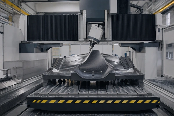
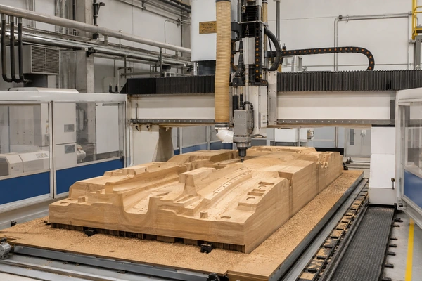
Delamination in composite machining is not a random cosmetic defect. It occurs when the cutting process loads the laminate faster or less evenly than the bond between its layers can tolerate. The familiar symptoms—lifted plies, frayed fibers, a chipped exit edge, or a damaged hole wall—usually point back to a small set of causes: weak local support, worn or unsuitable tooling, unstable cutting, excessive heat, or a poor entry-and-exit strategy. A sound process therefore starts with the laminate and the finished-edge requirement, not with a generic speed-and-feed table.
Read the Laminate Before Programming the Cut
“Composite” describes a family, not one material. Carbon-fiber laminate, glass-fiber laminate, sandwich construction, PMI or PET core, aramid honeycomb, and fiber-reinforced plastic do not fail in exactly the same way. Resin system, fiber direction, lay-up, skin thickness, core density, and cure quality all change the way a cutter meets the workpiece.
The drawing should identify more than the outside profile. Mark which edges will be visible, bonded, sealed, or hidden. Define the acceptable condition for the top face, bottom face, hole wall, and core. A buyer who only specifies a dimensional tolerance may receive a part that measures correctly but needs hours of edge repair before assembly.
Before a full production run, cut a representative coupon from the real production material. Include a corner, a hole, an exit edge, and any thin flange that is difficult to support. Record the tool, runout, cutting distance, fixture condition, and inspection result. That small trial is more useful than borrowing parameters from a different laminate.
Support the Exit Edge and Keep the Datum Stable
The cutter creates both in-plane and through-thickness forces. Delamination becomes more likely where the laminate can flex or where the final fibers have no support. A sacrificial backing plate can support a drilled or routed exit edge. For a contoured part, use shaped nests, vacuum fixtures, or distributed supports that hold the workpiece without forcing it into a distorted position.
Check for gaps before machining. A vacuum gauge can show that the fixture is pulling, yet a local bridge beneath a flange may still allow vibration. Clamps should restrain cutting forces without crushing a core or printing a hard point into a finished skin. If the part is thin or flexible, verify the datum again after clamping and after the roughing pass.
CHENcan’s product information notes optional vacuum-table arrangements for some configurations. The right fixture still depends on the actual part, so compare the work envelope, table layout, and access requirements across CHENcan 5-axis CNC centers rather than treating vacuum hold-down as a universal answer.
Choose Tool Geometry for the Failure Mode
A sharp edge lowers cutting force, but “sharp” is only the start of the decision. Compression-style geometry can help control both faces in some trimming operations. Specialized drills may reduce exit damage in holes. Abrasive laminates, however, change tool condition quickly, so a tool that produced a clean first part may not protect the twentieth.
Define a tool-life trigger before visible failure appears. It can be based on cutting distance, spindle load trend, edge inspection, or a combination of these signals. Keep the inspection method consistent: the same light, magnification, edge location, and acceptance sample. A vague instruction to change the tool “when dull” puts the decision too late in the process. This discipline matters in both composite trimming and hole-making.
Runout matters because one flute can take most of the load while the others rub. Verify the holder, collet, spindle taper, and installed tool as a system. If a trial shows heat discoloration, resin smearing, rapid wear, or a repeating wave on the edge, investigate tool condition and runout before changing several CAM variables at once.
Program Entry, Exit, and Fiber Direction Deliberately
Many failures happen when the cutter enters or leaves the laminate. Avoid allowing a finishing pass to burst through an unsupported corner at full engagement. Leave sacrificial stock, add a controlled lead-out, change the cutting direction, or sequence the last edge so that it remains supported as long as possible.
On a curved component, the effective fiber-cutting direction changes along the path. A strategy that is clean on one side may lift fibers after the contour reverses. Map the difficult zones in CAM and test them on the coupon. Separate roughing and finishing so the final pass removes a predictable allowance instead of alternating between rubbing and heavy engagement.
There is no honest universal spindle speed or feed rate for composite machining. Begin with the tool maker’s data for the exact material class and cutter, then validate chip formation, edge quality, temperature, and load on the actual laminate. Change one variable at a time and preserve the result in the process sheet.
Control Heat, Dust, and Chip Recutting
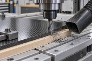
Fibers can be abrasive, and many resin systems lose edge quality when heat builds at the cut. Heat may come from rubbing, a worn edge, excessive runout, poor evacuation, or a toolpath that repeatedly recuts dust. The response should address the cause; simply slowing the feed can sometimes increase rubbing rather than solve it.
Capture dust close to the cutting zone and design the enclosure, extraction, filtration, housekeeping, and personal protection around the material supplier’s safety data and the factory’s risk assessment. CHENcan’s knowledge material describes its FC series as a fully enclosed platform for cutting and drilling carbon fiber, glass fiber, PMI, PET, EPS, aramid honeycomb, substitute wood, and plastics, with the enclosure intended to limit chip and dust spread. Broader material and process routes can be reviewed through CHENcan material and industry solutions.
Dust control is also a quality measure. Deposits under a flexible part can change its support; dust on a vacuum seal can reduce holding force; and recutting debris can scratch a finished face. Include fixture cleaning and seal inspection in the changeover, not only in end-of-shift housekeeping.
Decide Whether Three Axes or Five Are Actually Needed
A flat sheet profile with vertical holes may be best served by a rigid three-axis composite CNC machining process and a simple supported fixture. Five-axis motion becomes valuable when the part has compound trimming angles, angled drilling, deep side access, or a requirement to reduce refixturing. The advantage is access and setup control, not automatic immunity from delamination.
For large molds, panels, or structures, review reach, clearance, extraction routing, fixture access, and the swept volume of the head. Large-scale five-axis CNC options cover work beyond conventional machine envelopes, while custom five-axis configurations provide a starting point when a standard table, travel, or enclosure cannot accept the part. Any proposal should be checked against the real CAD model and process plan.
For simultaneous five-axis work, verify rotary-center calibration, tool length, postprocessor output, and RTCP behavior before the first production part. A smooth simulation does not prove that the physical tool center follows the intended surface. Calibration and acceptance testing belong in the manufacturing plan.
Use a Release Checklist That Measures Edge Quality
Before releasing a composite machining process, confirm the following items:
- Material: laminate designation, lay-up, cure state, thickness, core, and production lot are recorded.
- Geometry: visible, bonded, sealed, and hidden edges have separate acceptance criteria where needed.
- Fixture: the part is supported near exits and thin flanges, the datum remains stable, and vacuum or clamps are monitored.
- Tool: cutter type, holder, measured runout, new-tool benchmark, and replacement trigger are documented.
- CAM: entry, exit, fiber-direction changes, roughing allowance, finishing sequence, and collision clearance have been reviewed.
- Environment: enclosure, extraction, filter condition, housekeeping, and material-specific safety controls are ready.
- Inspection: the team checks both faces, hole exits, edge fibers, dimensions, and any required bond-preparation surface.
Machine accuracy is only one line on this list. Process capability comes from controlling the material, support, tool, path, and inspection together.
Match the Acceptance Test to the Real Part
An equipment acceptance test should reproduce the hardest features that will reach production: a representative laminate, the thinnest supported flange, the most difficult access angle, a drilled exit, and a realistic finishing allowance. Measure the edge under agreed lighting and magnification, not only with a caliper.
CHENcan describes laser interferometer, ballbar, rotary-axis, alignment, and RTCP calibration resources within its technical service and calibration support. Those tools can verify machine behavior, but the buyer should still define a material-specific cut trial. When the envelope, laminate, fixture, extraction, and finish criteria are ready, send the process requirements to CHENcan for configuration review.
FAQ
What is the most common cause of delamination during routing?
There is no single cause, but unsupported exit edges, worn tooling, and unstable engagement are frequent contributors. Inspect the location and direction of damage before changing parameters.
Can a five-axis machine eliminate delamination?
No. Five-axis access can reduce refixturing and align the tool more favorably, but tool condition, support, extraction, path strategy, and material variability still control the edge.
Should one cutting recipe be used for every carbon-fiber laminate?
No. Stack-up, resin, thickness, cure, and tool geometry change the result. Use supplier guidance as a starting point and prove the settings on production-equivalent coupons.
What should be inspected besides dimensions?
Inspect both faces, hole exits, frayed fibers, lifted plies, heat damage, resin smearing, core damage, and the condition of surfaces that will later be bonded or sealed.
Why keep a tool-life record if the part still measures correctly?
Edge damage and heat can appear before a dimensional trend becomes obvious. A tool-life record helps replace a cutter before hidden or costly finishing defects become routine.